This article, originally published in 2020, has been updated with the latest information.
Design for Manufacturing and Assembly (DFMA) – an engineering methodology that reduces time-to-market and total production costs by prioritizing ease of manufacturing and efficiency in assembly – is an essential component of any lean manufacturing strategy. When designing for sheet metal fabrication, engineers must take into consideration the physics of sheet metal and understand the processes on the shop floor.
DFMA for Sheet Metal Fabrication
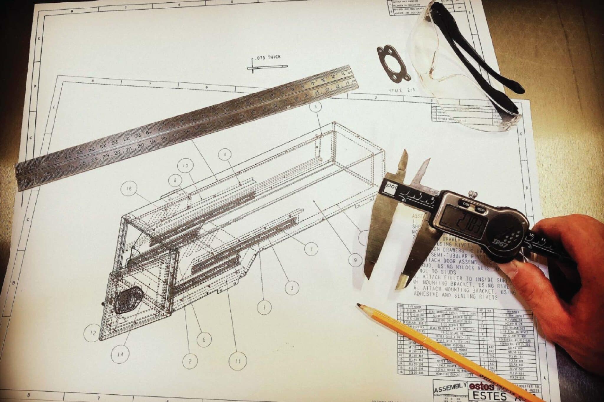
One of the biggest obstacles to overcome with sheet metal design is that modeling is based on an ideal state where everything is nominal and where execution of the design is assumed to be performed by perfect equipment and operators. CAD software is only a tool, and most off-the-shelf platforms don’t incorporate all the physics of metal bending and aren’t capable of anticipating what may be encountered on the shop floor.
Successfully designing for fabricating in the “real world” requires experience with sheet metal. Based on our decades of sheet metal fabrication experience, we have compiled some common design characteristics that must be considered in sheet metal design.
4 Main Design Characteristics to Consider with Sheet Metal Fabrication
1. Holes and Cutouts
Hole and Cutout Spacing
When CNC punching sheet metal, it is best to allow for two material thicknesses between punched features such as holes and cutouts. However, with laser cutting, it is feasible in most materials to limit the space between features to one material thickness; however, this should be avoided if possible.
Hole Diameter
A typical rule of thumb is that hole diameters should be at least one multiplied by the material thickness of your sheet metal part, whether the parts are punched or laser cut. For diameters close to the material thickness, a guided punch may be required. Hole diameters smaller than a material thickness would require either a machining operation or stubby-style tooling for turret press applications.
Hardware Holes and Placement
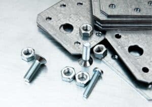
 The addition of hardware to a part (self-clinching nuts, rivets, nutserts, etc.) requires careful examination when placed near a bend. The outside edge of the hardware must be inboard of the tangent of the inside bend radius for proper seating. Also, access for hardware installation tooling must be considered.
Forming dimensions to holes or cutouts will not be as tight and consistent with laser cutting or punching processes as opposed to machining processes. Therefore, when matching hardware attachment holes (for rivets, screws, etc.) for panels that have multiple bends between hole centers, tolerances must be examined to ensure proper alignment of holes between mating panels. Sometimes slots or larger hole diameters for the attachment hardware are required.
Bending Near A Hole
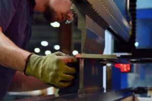
The distance between the edge of a hole or cutout and a bend is a function of the material thickness and the die width. Any part of a hole or cutout that lies within the “V” of a brake press die is not supported and will not bend with the rest of the flange. The edge will flare out, causing a distorted hole or cutout. Different materials have different inside bend radius limitations that must be accounted for when holes or cutouts are placed near a bend. Panel bender forming in lighter gauge sheet metal can successfully generate a much smaller dimension between a hole/cutout edge and a bend without disturbing the hole/cutout geometry. The tighter dimension is achieved through the wiping motion of the forming blade.
Related Article: DFMA Saves Money and Reduces Downstream Costs
2. Flanges
Corners and Adjacent Flanges
When designing panels that have single or double return flanges that meet at a corner or when a flange forms flush to the edge of an adjacent flange, space for bend spring back should be allowed. Some clearance is required to get a 90-degree bend when the required bend is flush with another bend on a part.
Welding Considerations

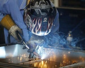
Corner underlaps/overlaps for adjacent flanges are designed differently for MIG, TIG, and particularly laser welding, with tolerances for laser welding being the tightest. Overlapping flanges can be laser welded using a keyhole pattern that allows the welding of two flanges when access for a fillet or butt weld isn’t permitted. Typically, laser welding requires some additional fixturing and is more justifiable for longer or repeating production runs.
Flanges With 45° Cuts
45° cuts on flanges should begin where the die supports the cut because any part of the diagonally cut flange lying within the “V” of the die will flare while forming. The panel bending mechanics of wiping the bends allows for a cut much closer to the bend.
3. Formed Channels
In some formed sections like a channel, the desired web dimension is much smaller than the height of the legs. With gooseneck press brake tooling, many tall and narrow sections are possible. These types of bends can also be accomplished at a panel bender, but the relationship between the web and the final leg must be determined.
4. Tonnage Limitations
 When punching or forming, tonnage limitations exist. On long bends with thick materials, the necessary tonnage to complete the bend must be considered. “V” die width, depending on availability, also influences tonnage. In CNC punching applications, the required stripping force for a hole/cutout in heavy and/or harder material may exceed the stripping capabilities of a particular CNC punching station. Tooling will have to be available in a larger-sized station whose tooling assemblies have more stripping pressure.
Partner with Estes for DFMA for Sheet Metal Fabrication
If you have questions or you’re looking for a partner with proven experience in cost-saving ideas for manufacturing, such as DFMA, Estes has the experience to deliver. Its engineers draw on their manufacturing expertise to translate ideas from concept to manufacturing while applying DFMA principles throughout the development process.


